4 Sketching and Drawing Techniques
Camosun College
Learning Objectives
By the end of this chapter, you should be able to:
- use sketching skills to draw straight lines and round circles
- apply views to sketch 3d representations of objects
Freehand sketching is a very useful skill that can be mastered with practice and by following a few guidelines. The ability to interpret drawings is complemented by the ability to sketch information from a drawing to take to your work location. Sketching is also a valuable tool when no drawing is available and you need to communicate job information to someone else.
For freehand sketching, you require a pad of graph paper (8 ½” × 11″ sheets with a 5 mm or ¼“ grid), a sharp HB pencil, and an eraser. Do not begin any sketch with a dull pencil.
Sketching technique
Sketching provides a quick and simple way to express ideas and to communicate the shape and general size of an object.
Sketching parallel lines
Start by drawing lines that are parallel to the edges of the paper, such as a border line and title block. Use your finger as a guide when you draw along the grid line on the sketch pad (Figure 1). If you let the end of your little finger run down the edge of the paper pad as you draw, this will steady your hand and make it easier to get a straight line.
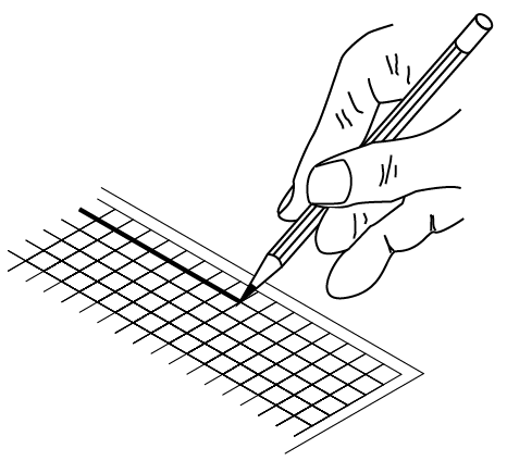
Figure 1 – Sketching a parallel vertical line
Sketching non-parallel lines
When you are sketching lines that are not parallel to the sides of the paper, turn the paper around so that the line you wish to draw is either straight up and down in front of you or straight across the sheet of paper.
It is much easier to draw lines this way, rather than at an angle across the sheet. Let the side of your little finger rest on the paper as you draw. This will help you steady your hand (Figure 2).
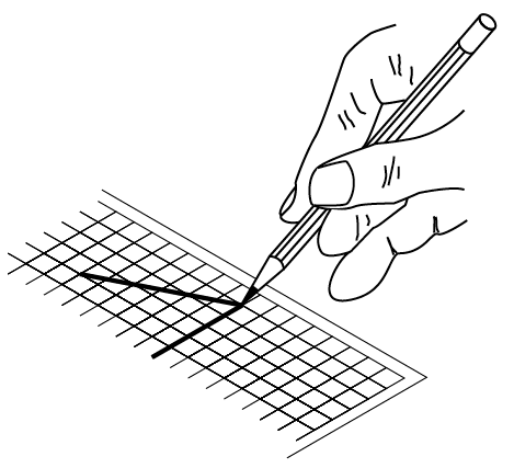
Figure 2 – Sketching a horizontal line
Sketching a rectangle
Locate the corners of the rectangle first. Then place your paper in a comfortable position for sketching and sketch downward for vertical lines and left to right for horizontal lines. Use the grid lines as a guide to maintain lines parallel and at 90 degrees to each other (Figure 3).
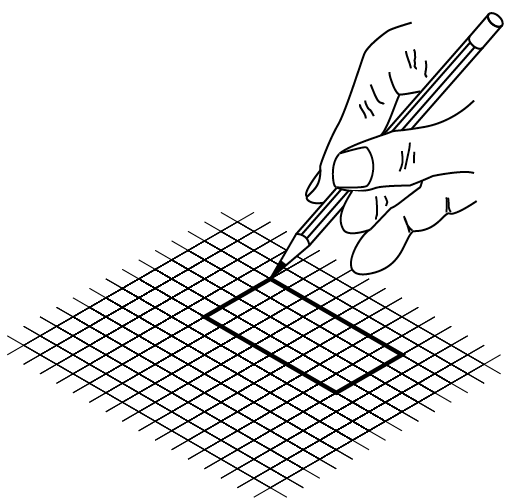
Figure 3 – Sketching a rectangle
Sketching a circle
First, locate the centre of the circle (Figure 4), and then very lightly box in the size of the circle (using the diameter as a guide), as in the top right. Sketch in the circle, one quarter at a time, as shown in the bottom row, left to right. You may find it necessary at first to add light points along the projected circumference to help guide you through each quarter. Remember to move your sketch pad so that you can maintain a comfortable sketching position.
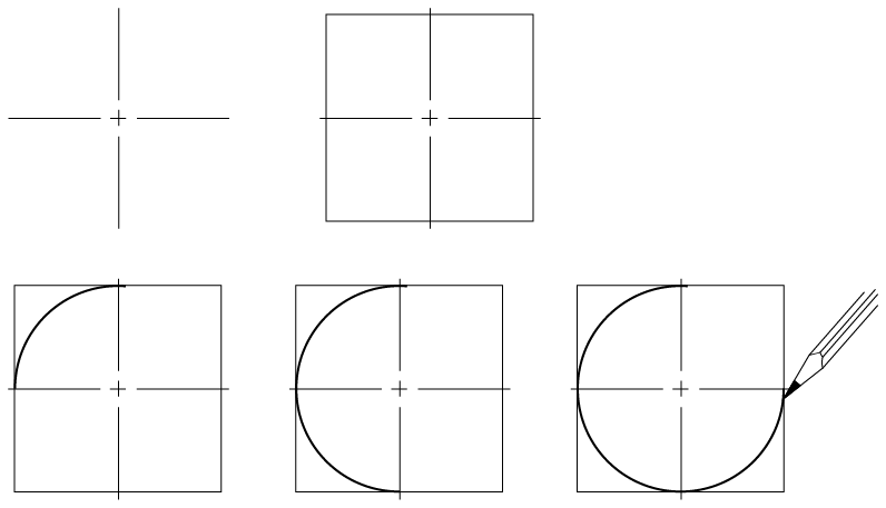
Figure 4 – Sketching a circle
Sketching to approximate scale
In Figure 5, the full-size square is on the left. The centre square is half size, and the right square is quarter size. Note that centre and right squares are the same shape as the left square, only smaller.
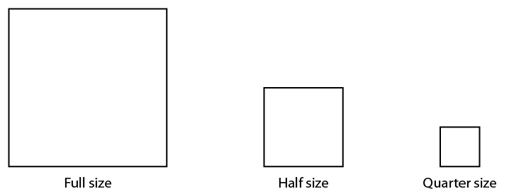
Figure 5 – Sketching to scale
When you are sketching freehand, your sketches should reflect the true shapes of objects as much as possible. If you use grid paper, it is not difficult to sketch to an approximate scale. Assume that the object in Figure 6 is shown full size. As it is necessary to show all orthographic views on the same sheet of paper, the views must be scaled. Figure 7 shows the views at approximately one-half the original size.
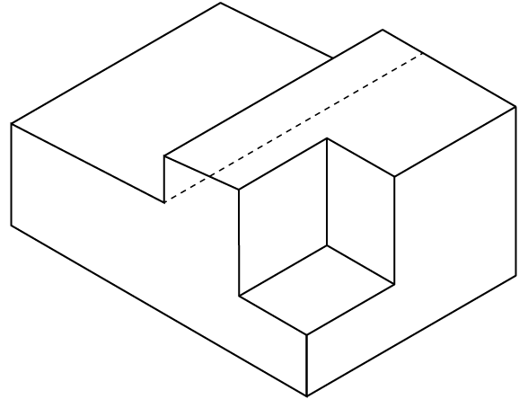
Figure 6 – Full-size isometric object
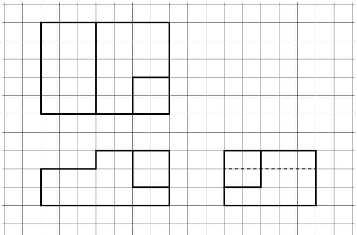
Figure 7 – Scale orthographic projections
Make isometric sketches of simple rectangular objects
Isometric sketches are useful because they are easy to draw and clearly represent an object or system. This clarity comes from using directional lines to represent the three dimensions of length, width, and height, much like a picture.
Construction methods
The following steps explain how to draw an isometric cube. The three dimensions of length, width, and height are drawn along the isometric axes shown in Figure 8. The lengths of objects running parallel to these axes can be drawn to scale. Lines at other angles will not be to scale.
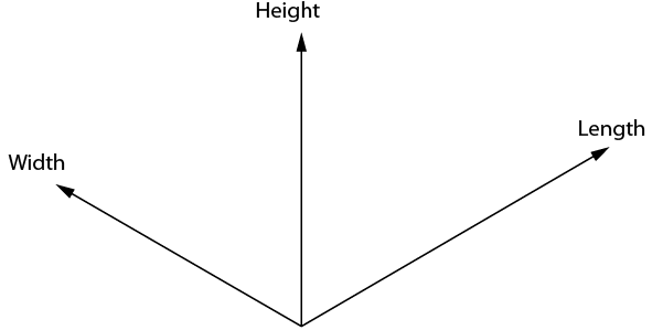
Figure 8 – Isometric axes
Draw a small star-shaped axis on the bottom corner of your grid paper. The sloping axes should be drawn at a 30° degree angle from the horizontal grid line. The vertical axis of the star indicates height (H) or depth (D), and the two sloping axes indicate the length (L) and the width (W) of the rectangle. The vertical axis can be used as a guide when making lines on your drawing. Notice we have labelled the points on the star in Figure 9. These labels can change depending on the view that you may want when drawing a stationary object. The bottom two horizontal points indicate the view that is being drawn. In this case, we would be creating a front-right view.
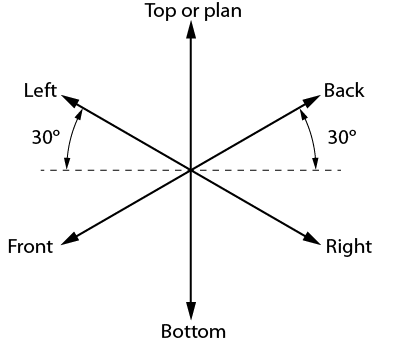
Figure 9 – Step 1: Isometric guide for a front-right view
Sketch the top of the block by drawing two lines, one parallel to L and one parallel to W (Figure 10).
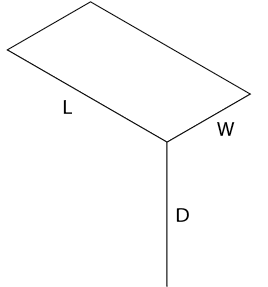
Figure 10 – Step 2: Isometric view of the top surface of a rectangular block
Sketch two lines, one parallel to L and one parallel to D as shown in Figure 11.
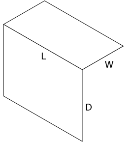
Figure 11 – Step 3: Lines parallel to L and D
Sketch two lines, one parallel to W and one parallel to D, to complete the outline of the rectangular block as shown in Figure 12. Begin with light construction lines so that you can make any necessary adjustments before darkening them. The finished isometric sketch is shown in Figure 13.
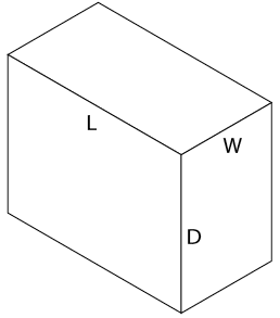
Figure 12 – Step 4: Completed outline of the rectangular block
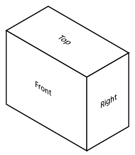
Figure 13 – Completed isometric sketch
Sketching irregular shapes with isometric lines
Not all rectangular objects are as simple as the block you have just sketched. Sometimes the shapes are irregular and have cut-out sections or some sides longer than others. All rectangular objects can be fitted into a box having the maximum length (L), width (W), and depth (D). Begin by sketching a light outline of a basic box that is the size of the object to be drawn.
As an example, consider the object shown in the three-view orthographic sketch in Figure 14. To produce an isometric sketch of this object, you need to find the maximum L, W, and D for the containing box (Figure 14). In this case:
L = 5 grid spaces
W = 3 grid spaces
D = 3 grid spaces
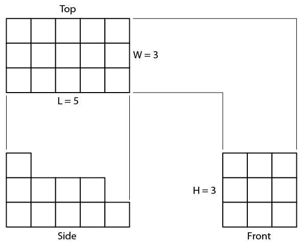
Figure 14 – Orthographic views
Sketch a light outline of the basic rectangular box to the required size, as shown in Figure 15.
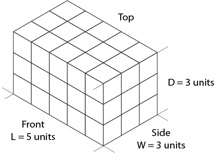
Figure 15 – Basic outline
The front view shows the outline most clearly. Place this view on the front surface of the isometric box. Use the dimension given in the front view of Figure 14 and mark the number of units indicated along the axes L and D (Figure 16).
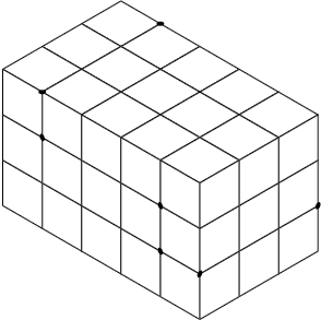
Figure 16 – Location of marks on axes
Lightly sketch lines parallel to the L and D axes from the marked points on the front surface (Figure 17). The step outline is drawn more heavily to emphasize the profile of the object, once you are sure your sketch is correct.
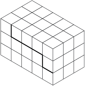
Figure 17 – Location of main features
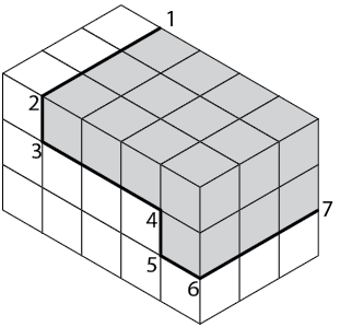
Figure 18 – Location of outer surfaces
Sketch in a series of lines parallel to the axes (L, W, and D) from the corners numbered 1 to 7 (Figure 18). These lines establish the stepped outline as shown in Figure 19.
When you are sure your isometric sketch is correct, erase all unnecessary construction lines and darken the object lines. Your completed sketch of the rectangular object should be similar to that in Figure 20.
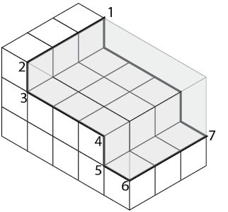
Figure 19 – Internal features
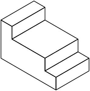
Figure 20 – Completed sketch
Sketching figures with non-isometric lines
Figure 21 shows an object that is basically rectangular but has one face machined at an angle. You can easily construct an isometric sketch of the basic rectangular block. To show the machined face, it is necessary to plot the appropriate points of intersection and join those points to produce the correct angle.
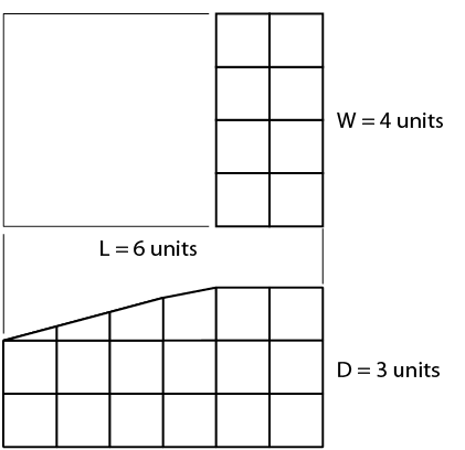
Figure 21 – Rectangle with face machined at an angle
Sketch a light outline of the basic rectangular block, using the size measurements given in Figure 21. Mark the number of units indicated along the length (L) and the depth (D), as shown in Figure 22.
Lightly sketch lines parallel to the original block outlines from the marked points on the front and side surfaces, as shown in Figure 23.
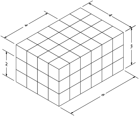
Figure 22 – Rectangle with units marked along L and D
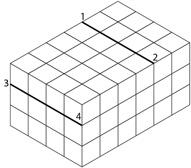
Figure 23 – Lines sketched parallel to original block outline
Join the two points on the front face and the two ends of the lines you have just sketched across the object (Figure 24). Once you are sure your sketch is correct, erase the light lines that originally outlined the block and darken the outline of the completed block as shown in Figure 25.
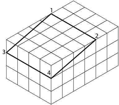
Figure 24 – Front face
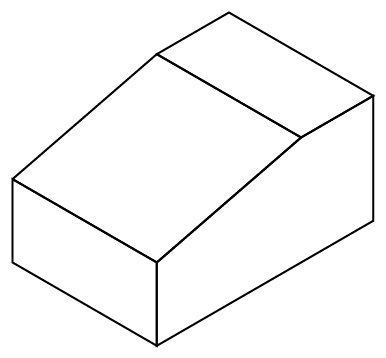
Figure 25 – Completed block
Self Test
![]() Now complete the Learning Task Self-Test.
Now complete the Learning Task Self-Test.
![]() Key Takeaways
Key Takeaways
- Practical techniques can be learned and practised to make your freehand sketches neater and easier for others to visualize.
- Use grid paper underneath, or draw axis lines, when sketching pictorial views to help guide how you represent depth in your drawing.
