2 Lines, lettering, and Dimensions
Camosun College
Learning Objectives
By the end of this chapter, you should be able to:
- identify line types used in technical drawings
- interpret dimensioning on technical drawings
- use professional lettering techniques
The purpose of technical drawings is to convey objective facts, whereas artistic drawings convey an emotion or artistic sensitivity in some way.
Technical drawings and sketches need to display simplicity and uniformity, and they must be executed with speed. Technical drawing has evolved into a language that uses an extensive set of conventions to convey information very precisely, with very little ambiguity.
Standardization is also very important, as it aids internationalization; that is, people from different countries who speak different languages can read the same engineering drawing and interpret it the same way. To that end, drawings should be as free of notes and abbreviations as possible so that the meaning is conveyed graphically.
Line styles and types
Standard lines have been developed so that every drawing or sketch conveys the same meaning to everyone. In order to convey that meaning, the lines used in technical drawings have both a definite pattern and a definite thickness. Some lines are complete and others are broken. Some lines are thick and others are thin. A visible line, for example, is used to show the edges (or “outline”) of an object and to make it stand out for easy reading. This line is made thick and dark. On the other hand, a centre line, which locates the precise centre of a hole or shaft, is drawn thin and made with long and short dashes. This makes it easily distinguishable from the visible line.
When you draw, use a fairly sharp pencil of the correct grade and try to maintain an even, consistent pressure to make it easier for you to produce acceptable lines (Figure 1).
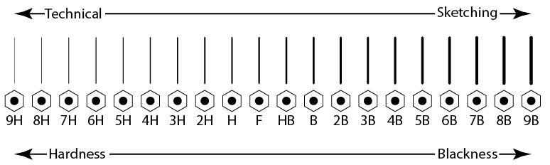
Figure 1 – Lead grade and usage
To properly read and interpret drawings, you must know the meaning of each line and understand how each is used to construct a drawing. The ten most common are often referred to as the “alphabet of lines.” Let’s look at an explanation and example of each type. Figure 2 shows these ten line types and how to draw them.

Figure 2 – Line Types and Techniques
Object lines
Object lines (Figure 3) are the most common lines used in drawings. These thick, solid lines show the visible edges, corners, and surfaces of a part. Object lines stand out on the drawing and clearly define the outline and features of the object.
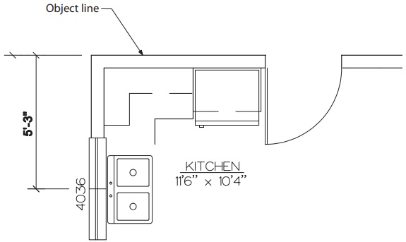
Figure 3 – Object lines
Hidden lines
Hidden lines (Figure 4) are used to show edges and surfaces that are not visible in a view. These lines are drawn as thin, evenly spaced dashes. A surface or edge that is shown in one view with an object line will be shown in another view with a hidden line.
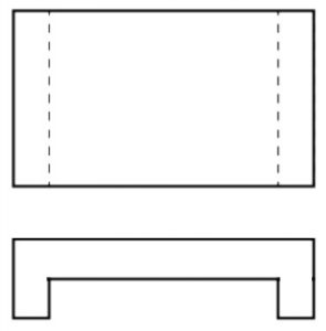
Figure 4 – Hidden lines
Centre lines
Centre lines (Figure 5) are used in drawings for several different applications. The meaning of a centre line is normally determined by how it is used. Centre lines are thin, alternating long and short dashes that are generally used to show hole centres and centre positions of rounded features, such as arcs and radii. Arcs are sections of a circle, and radii are rounded corners or edges of a part. Centre lines can also show the symmetry of an object.
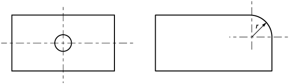
Figure 5 – Centre lines
Dimension and extension lines
Dimension and extension lines (Figure 6) are thin, solid lines that show the direction, length, and limits of the dimensions of a part. Dimension lines are drawn with an arrowhead at both ends.
Extension lines are drawn close to, but never touching, the edges or surface they limit. They should be perpendicular, or at right angles, to the dimension line. The length of extension lines is generally suited to the number of dimensions they limit.
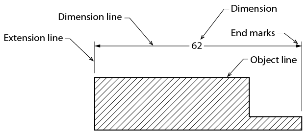
Figure 6 – Dimension and extension lines
Leader lines
Leader lines (Figure 7) show information such as dimensional notes, material specifications, and process notes. These lines are normally drawn as thin, solid lines with an arrowhead at one end. They are bent or angled at the start, but should always end horizontal at the notation. When leader lines reference a surface, a dot is used instead of an arrowhead.
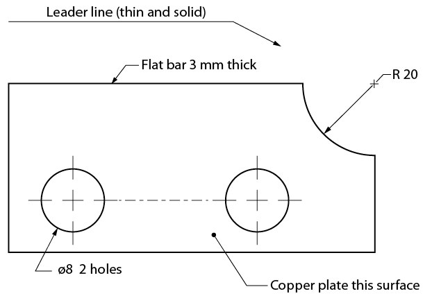
Figure 7 – Leader lines
Note that the symbol ø is used to indicate a diameter rather than the abbreviation “DIA.” The number that immediately follows this symbol is the diameter of the hole, followed by the number of holes that must be drilled to that dimension.
Phantom lines
Like centre lines, phantom lines (Figure 8) are used for several purposes in blueprints. Phantom lines are used to show alternate positions for moving parts and the positions of related or adjacent parts, and to eliminate repeated details. Phantom lines are drawn as thin, alternating long dashes separated by two short dashes.
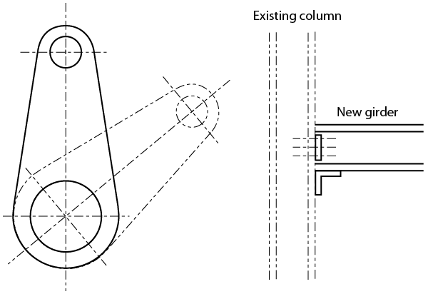
Figure 8 – Phantom lines
Cutting plane lines
Cutting plane lines (Figure 9) show the location and path of imaginary cuts made through parts to show internal details. In most cases, sectional views (or views that show complicated internal details of a part) are indicated by using a cutting plane line. These lines are thick, alternating long lines separated by two short dashes. The arrowheads at each end show the viewing direction of the related sectional view. The two main types of cutting plane lines are the straight and the offset.
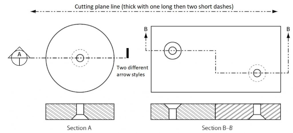
Figure 9 – Cutting plane lines
Section lines or hatch patterns
Section lines, also known as hatch patterns, (Figure 10) indicate the surfaces in a sectional view as they would appear if the part were actually cut along the cutting plane line. These are solid lines that are normally drawn at 45-degree angles. Different symbols are used to represent different types of materials.
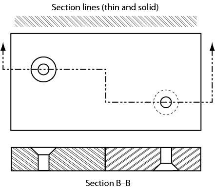
Figure 10 – Section lines combined with cutting plane lines
Break lines
Break lines are drawn to show that a part has been shortened to reduce its size on the drawing. The two variations of break lines common to blueprints are the long break line and the short break line (Figure 11). Long break lines are thin solid lines that have zigzags to indicate a break. Short break lines are thick, wavy solid lines that are drawn freehand. When either of these break lines is used to shorten an object, you can assume that the section removed from the part is identical to the portions shown on either side of the break.
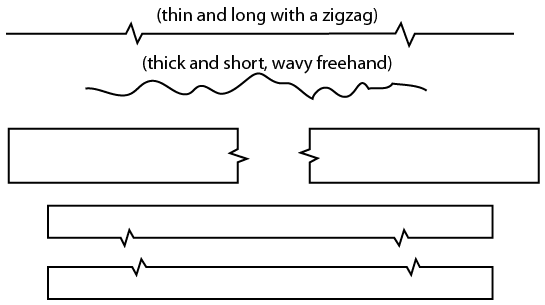
Figure 11 – Break line
Self Test
![]() Now complete this mid-chapter self-test.
Now complete this mid-chapter self-test.
Standard lettering
The letters and numbers on a drawing or sketch are as important as the lines. Scribbled, smudged, or badly written letters and numbers can become impossible to read. This may lead to time-consuming and costly errors. Lettering is necessary to describe:
- the name or title of a drawing
- when it was made
- the scale
- who sketched it
- the dimensions
- the special notations that describe the size
- the materials to be used
- the construction methods
The American Standard Vertical letters (Figure 12) have become the most accepted style of lettering used in the production of manual drafting. This lettering is a Gothic sans serif script, formed by a series of short strokes.
Font styles and sizes may vary in computer drafting. Note that all letters are written as capital (upper case) letters. Practise these characters, concentrating on forming the correct shape. Remember that letters and numbers must be black so that they will stand out and be easy to read. Lettering and figures should have the same weight and darkness as hidden lines.
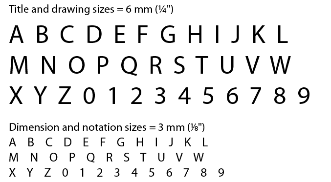
Figure 12 – Standard lettering
Abbreviations
Abbreviations are commonly used to help simplify a drawing and conserve space. Although many fields share common abbreviation conventions, there are also field- or trades-specific conventions that you will see as you become more specialized. Here is a common list of abbreviations that are used on drawings. Each trade will have specific abbreviations from this list, and therefore a set of drawings will usually include an abbreviation key.
|
AB anchor bolt ABT about AUX auxiliary BC bolt circle BBE bevel both ends BCD bolt circle diameter BOE bevel one end BE both ends BL baseline BM bench mark Btm bottom BP base plate B/P blueprint BLD blind C/C centre to centre COL column CPLG coupling CS carbon steel C/W complete with CYL cylinder DIA diameter DIAG diagonal DIM dimension DWG drawing EA each EL elevation EXT external F/F face to face FF flat face FLG flange FW fillet weld Ga gauge Galv galvanized HVY heavy HH hex head HR hot rolled HT heat treatment HLS holes |
HSS hollow structural steel ID inside diameter IN inches INT internal ISO International Standards Org. KP kick plate LH left hand LAT lateral LR long radius LG long MB machine bolt MS mild steel MIN minimum MAX maximum MAT’L material MISC miscellaneous NC national course NF national fine NO number MOM nominal NTS not to scale NPS nominal pipe size NPT national pipe thread O/C on centre OA overall OD outside diameter OR outside radius OPP opposite PAT pattern PBE plain both ends POE plain one end PSI pounds per square inch PROJ project RD running dimension R or Rad radius RND round |
REF reference REQ’D required REV revision RF raised face RH right hand SCH schedule SI International System of Units SPECS specifications SQ square SM seam SMLS seamless S/S seam to seam SO slip on SEC section STD standard SS stainless steel SYM symmetrical T top T&B top and bottom T&C threaded and coupled THD threaded TBE threaded both ends TOE threaded one end THK thick TOL tolerance TOC top of concrete TOS top of steel TYP typical U/N unless noted VERT vertical WD working drawing WP working point WT weight W/O without XH extra heavy XS extra strong |
Figure 13 shows a simple drawing. Notice that the dimensions are given between arrows that point to extension lines. By using this method, the dimensions do not get in the way of the drawing. One extension line can be used for several dimensions. Notice also that the titles require larger letter sizes than those used for dimensions and notations. It is important that the title and sketch number stand out, as shown in Figure 13. When you begin lettering, you may wish to use very light lettering guide lines to ensure uniformity in lettering size and alignment.
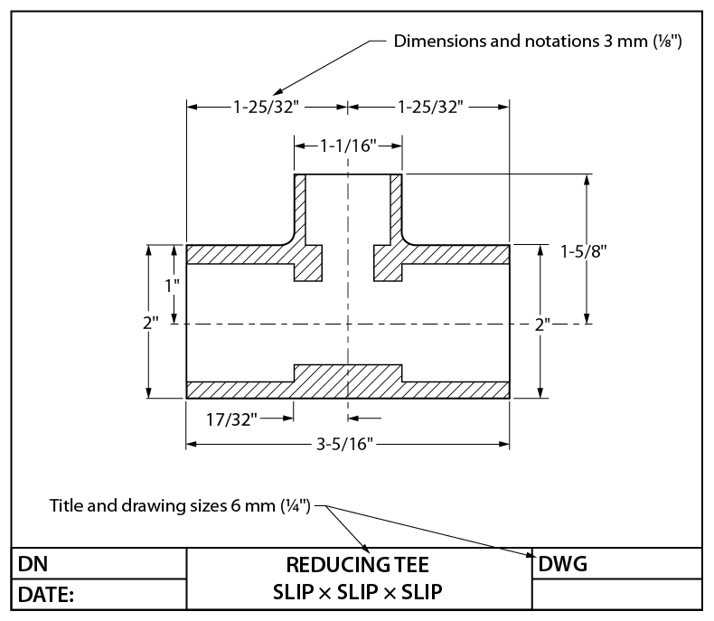
Figure 13 – Standard lettering sizes
Principles of dimensioning
A good sketch of an object is one that you can use as a blueprint to manufacture the object. Your sketch must show all the necessary dimensions of the part, locate any features it may have (such as holes and slots), give information on the material it is to be made from, and if necessary, stipulate the processes to be used in the manufacture of the object.
Three principles of dimensioning must be followed:
- Do not leave any size, shape, or material in doubt.
- To avoid confusion and the possibility of error, no dimension should be repeated twice on any sketch or drawing.
- Dimensions and notations must be placed on the sketch where they can be clearly and easily read.
Consider Figure 14 and note whether these three dimensioning principles have been followed.
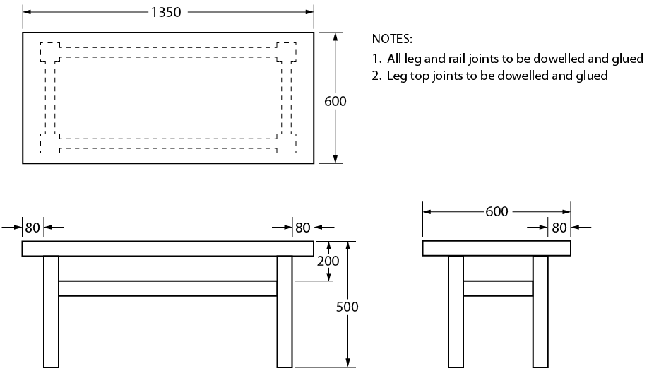
Figure 14 – Shop table
Although the dimensions and notations are clear and easy to read in Figure 14, the following points should be made:
- Leg and rail sizes have not been shown.
- The thickness of the top has not been given.
- The material has not been given as a notation.
- The 600 dimension has been repeated.
- The type of finish to be used has not been given.
- Note 2 is redundant.
The sketch of the shop table is far from complete, and the table could not be made without a lot of guesswork. Figure 15, on the other hand, shows a completed sketch that, along with the necessary notes and dimension information, can be readily used for construction purposes.
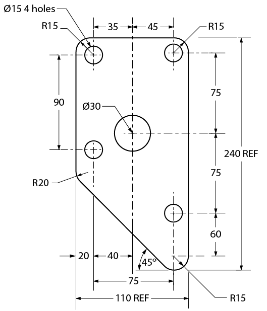
Figure 15 – Dimensioning
Rules of dimensioning
For most objects, there are three types of dimensions:
- size dimensions
- location dimensions
- notation dimensions
Figure 16 illustrates the difference between size and location dimensions. (S = size dimension and L = location dimension).
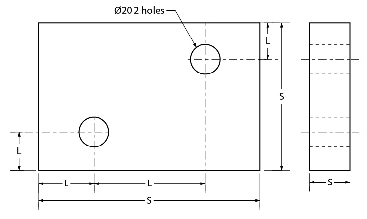
Figure 16 – Shim plate
Size dimensions are necessary so that the material size of the object can be determined. Location dimensions are necessary so that parts, holes, or other features can be positioned in or on the object. Notation dimensions describe the part, hole, or other feature with a short note such as the “ø20 2 holes” notation (see Figure 16). Keep these points in mind:
- Keep all dimension lines at least 10 mm (3/8“) clear of object lines wherever possible.
- Try to group related dimensions rather than scattering them.
- Try to keep dimensions off the views themselves.
- Separate one line of dimensions from another line of dimensions or from a notation by a space of at least 10 mm (3/8“).
- Leave a space of approximately 3 mm (1/8“) between the object outline and the beginning of any extension line.
- Keep arrowheads slim and neat.
- Never dimension to a hidden line.
- Draw leader lines at an angle when intersecting object lines to avoid confusing them with extension lines.
Figure 17 illustrates good placement of dimensions and notations. Note the placement of extension lines and the use of centre lines to locate features such as holes. Also, note the shape and size of arrowheads.
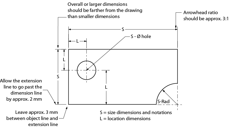
Figure 17 – Extension line usage
Dimensioning systems
Two systems are used for dimensioning drawings. They are the aligned and the unidirectional systems. Figure 18 shows examples of both systems. As you can see, the aligned system requires that you turn the drawing on its side, whereas the unidirectional system may be read from the normal reading position. For most drawings, the unidirectional system is preferred, as it is easier to read; however, architectural drawings still use the aligned system.
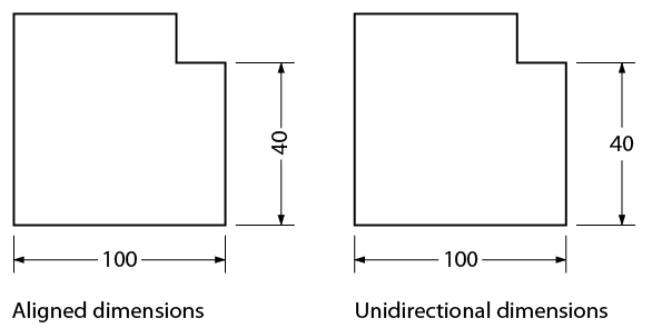
Figure 18 – Dimensioning systems
Systems of measurement
You may be required to sketch or read drawings constructed with either metric (SI) or imperial dimensions. You may also encounter drawings that are dual-dimensioned and contain both systems of measurement on the same drawing.
SI system of measurement
The SI system of measurement has become the official standard in Canada. It is common practice on shop drawings to express all metric dimensions in millimetres. Figure 19 shows a detailed drawing for a connector arm using metric measurements. All metric drawings should contain a note specifying that all dimensions are in millimetres.
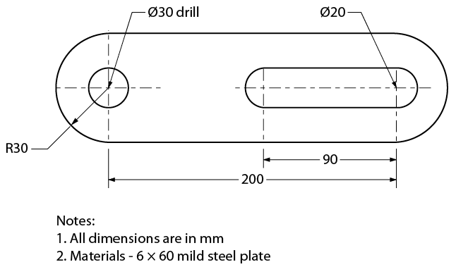
Figure 19 – Connector arm – metric measurement
Imperial system of measurement
An imperial drawing may use the decimal-inch system, the fractional-inch system, or feet and inches.
- In the decimal-inch system, very accurate dimensions for items such as machine parts are expressed as decimals of an inch, such as 0.005“. In words, this reads as five one-thousandths of an inch.
- In the fraction-inch system, dimensions for things such as steel and lumber sizes are expressed as inches and fractions of an inch from as small as 1/64“ (Figure 20). Most drawings that are dimensioned in the imperial system will use the fraction-inch system.
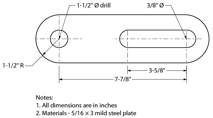
Figure 20 – Connector arm – imperial measurement
In the feet-inch system (Figure 21), the dimensions of large structures such as machine frames and buildings are expressed in feet and inches, such as 2‘-6“ (two feet, six inches).
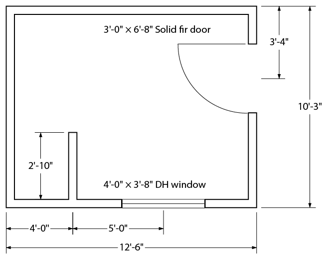
Figure 21 – Fuel storage shed
Dimensioning orthographic sketches
The following are rules and procedures for dimensioning single- and multi-view sketches:
- Place dimensions on views that show parts of features as solid outlines. Avoid dimensioning hidden lines wherever possible.
- Try to keep dimensions between views. Leave adequate room between views when you begin your sketch.
- Keep the smallest dimensions nearest to the object outline.
- Diameters in metric measurement should be denoted on a sketch using the symbol ø (e.g., ø20 – 2 holes). A radius should be denoted using the letter R (e.g., R 25).
- Diameters in imperial measurements may be denoted on a sketch by the symbol ø or the abbreviation DIA (e.g., 3“ ø DRILL or 4½“ DIA). A radius may be denoted using the letter R or the abbreviation RAD (e.g., 3“ R or 6½“ RAD).
- Arrows carrying notations should always point toward the centre of circular objects.
- Arrows should always point toward a circle centre when dimensioning a diameter and away from the centre when dimensioning a radius.
Self Test
![]() Now complete the Learning Task Self-Test.
Now complete the Learning Task Self-Test.
![]() Key Takeaways
Key Takeaways
- Technical drawings convey objective facts, and those facts are represented by the lines and text on the drawing.
- Different styles and thicknesses of lines are used to convey different aspects of the object being drawn.
- Text must be printed and legible. Dimensions must be clearly located with extension lines and arrows.
