8 Determine Dimensions from Drawings
Camosun College
Learning Objectives
By the end of this chapter, you should be able to:
- Use scale rulers to determine actual dimensions from drawings
Scale drawings are accurate and convenient visual representations made and used by engineers, architects, and people in the construction trades. The accuracy is achieved because the drawing is proportional to the real thing. The convenience comes from the size of the drawing. It is large enough to provide the desired detail but small enough to be handy.
The flexibility to draw proportionally in different sizes is provided by scales. For the purposes of representation, we will only be concerned with reduction scales. Reduction scales make the drawing smaller than the object. The kinds of rulers we will be discussing for making scaled drawings are the architect’s scale and the metric scale, both shown in Figure 1.
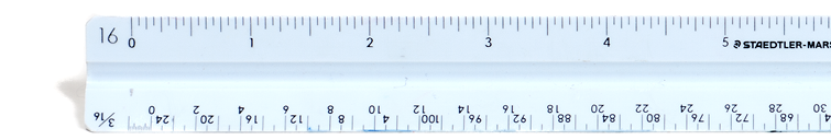
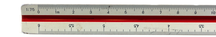
Figure 1 – Architect’s and metric rulers
The scale of the drawing is always written on the drawing, unless the drawing is not drawn to scale. In the latter case, this will be indicated by the “not to scale” abbreviation (NTS). The scale is the ratio of the size of the drawing to the object. For drawings smaller than the object, the ratio is that of a smaller distance to a larger one.
The architect’s scales use ratios of inches to a foot. The most common architect’s scale used is 1/4 inch to the foot, written on drawings as:
Scale 1/4“ = 1‘-0“
This means that a line 1/4“ long on the drawing represents an object that is one foot long. At the same scale, a line 1½“ long represents an object 6‘ long, because 1½“ contains 6 quarter-inches.
Metric scale ratios use the same units in both ratio terms, resulting in an expression of how many times smaller than the object the drawing is. For example, the standard metric scale ratio that corresponds approximately to ¼“ = 1‘-0“ is written on drawings as “Scale 1:50.”
This means that the object is 50 times as large as the drawing, so that 50 mm on the object is represented by 1 mm on the drawing. For another example, 30 mm on the drawing represents 50 × 30 mm = 1500 mm (or 1.5 metres) on the object.
Figure 2 lists the scale ratios used for building plans and construction drawings in both metric and the approximate equivalent architectural scale ratios.
|
Type of Drawing |
Common Metric Ratios |
Imperial Equivalents and Ratios |
Use |
|
|
Site plan |
1:500 1:200 |
1″ = 40′-0″ |
1:480 1:192 |
|
|
Sketch plans |
1:200 |
1/16” =1′-0″ |
1:192 |
|
|
General locations |
1:100 |
1/8” =1′-0″ |
1:96 |
|
|
Drawings |
1:50 |
1/4“ =1′-0″ |
1:48 |
|
|
Construction details |
1:20 |
1/2” =1′-0″ |
1:24 |
|
Figure 2 – Preferred scales for building drawings
Architect’s (imperial) scales
Traditional architectural measurements of length are written very precisely in feet and inches using the appropriate symbols for feet and inches separated by a dash (e.g., 4‘-3 ½“ and 7‘-0″). This is the way that all imperial measurements are written on construction drawings.
Listed below are the scales found on the architect’s triangular scale ruler.
- 3/32” =1′-0″
- 3/16” = 1′-0″
- 1/8” = 1′-0″
- ¼” = 1′-0″
- ¾” = 1′-0″
- 3/8” = 1′-0″
- 1″ =1′-0″
- ½” = 1′-0″
- 1½” = 1′-0″
- 3″ = 1′-0″
- 1″ = 1″ (full size—use the scale labelled 16)
Figure 3 shows one face of an architect’s imperial triangular scale ruler. There are two edges on each face and each edge contains two scales that run in opposite directions. At each end of an edge, a number or fraction indicates the distance in inches that represents one foot. The top edge is in eighths of an inch from left to right, and in quarters of an inch from right to left. Note that the 1/8“ scale from 0 to the right end represents 95 feet, and the ¼“ scale from 0 to the left end represents 47 feet.
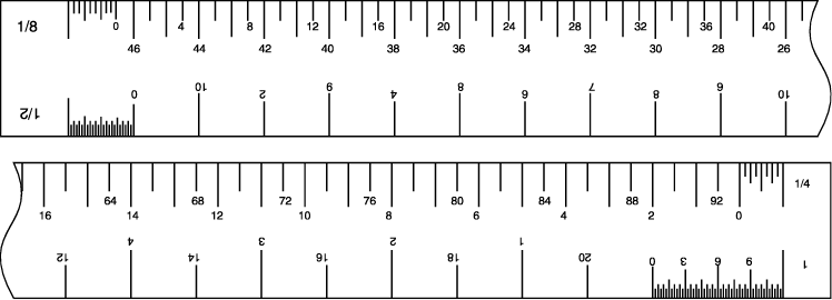
Figure 3 – One face of an architect’s ruler (NTS)
At each end, between the zero and the number indicating scale, the length representing one foot is subdivided into 6, 12, 24, or more parts to indicate inches and, in some scales, fractions of an inch. For example, each of the six marks on the 1/8“ scale represents two inches, while each mark equals a quarter of an inch on the 1“ reduction scale and one inch on the ¼“ scale.
Now look at the 1½“ scale in Figure 4. The subdivided unit is divided into inches and fractions of an inch. Reading left from the zero, notice the figures 3, 6, and 9, which represent measurements of 3“, 6“, and 9“. From the zero to the first long mark represents 1“. Between the zero and the one-inch mark there are four spaces, each of which represent one-quarter of an inch.
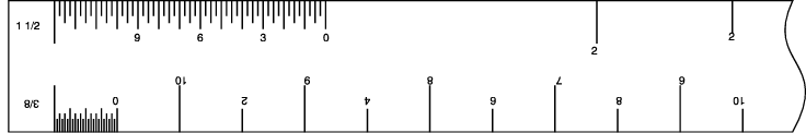
Figure 4 – Units in an architect’s scale ruler (NTS)
Piping drawings usually use a 1/8“ scale for larger buildings, a ¼“ scale for smaller buildings and houses, and a ½“ scale for details. Each drawing will state in the title box the scale that is used. Sometimes when special details are given, the scale is placed directly under the detail.
To draw or measure a length to scale, first find the edge of the ruler containing the scale. One end of the length will rest exactly on one of the foot marks of the scale, and the other end should rest either on the zero marker or somewhere on the inch subdivision of the scale. The length can then be marked and drawn or read off from a drawing.
Figures 5 and 6 demonstrate this manner of reading dimensions from four of the ratios on the architect’s scale.
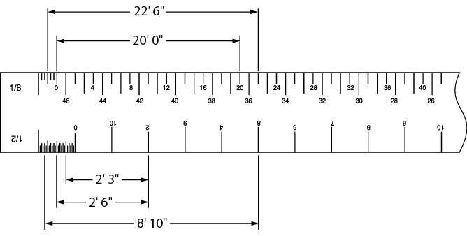
Figure 5 – Reading dimensions using an architect’s ruler (NTS)
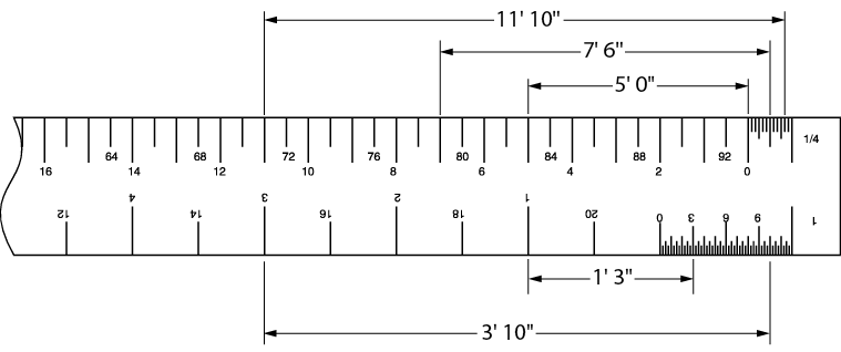
Figure 6 – Reading dimensions using an architect’s ruler (NTS)
 Architectural units have feet divided into inches, whereas engineering units divide feet into tenths and hundredths. Engineers’ scales are not used to make piping drawings.
Metric scales
A triangular metric scale is similar to the architectural scale in that it has six edges, but it has only one scale ratio per edge. The ratio is marked at the left end of the scale. For example, the scale of 1:50 means that 1 mm on the drawing represents 50 mm on the object. This means that the object is 50 times larger than the drawing of it. An object 450 mm long would be represented by a line 9 mm long (450 mm/50).
Figure 7 shows one of the three sides of a metric scale. The scale labelled 1:50 is read from left to right, from 0 to 15 m. The 1:5 scale (on the bottom) can also be read from left to right (0 to 600 mm) by turning the scale around.
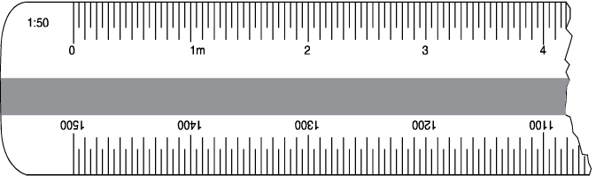
Figure 7 – One side of a metric ruler
If the ratio is 1:1, it means that 1 mm on the drawing represents 1 mm. In other words, the object in the drawing is being drawn to its actual size.
The ratios most often used in drawings are 1:100 for larger buildings, 1:50 for smaller buildings, and 1:20 for details.
You will notice that all the edges on a metric scale are marked with spaces that are 1 mm apart, similar to a metric tape measure. The difference is that each edge is marked off or labelled according to a different ratio, so that proportionate lengths are read directly from the scale. This eliminates the need to calculate dimensions.
Figure 8 shows common metric scales for comparison. Notice that all the scales shown are labelled in metres and that 0.5 m = 500 mm. All the scales in Figure 8 are marked at the scaled position of 250 mm.
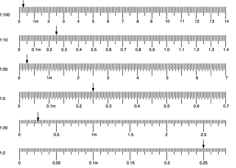
Figure 8- Metric scales marked at 250 mm
The length of an object represented on a drawing in a metric scale is found by measuring the drawn object with a metric ruler of the proper scale. You can also measure the drawing with any metric tape measure and multiply that by the scale ratio.
Obtain dimensions from drawings
The best way to get exact dimensions from drawings is to use the explicit dimensions (in millimeters or in feet and inches) written between the dimension lines. Any measurements that you need should be somewhere on the drawings. Drawings normally only give each dimension once. If there are a number of parallel lengths, only one will have a measurement. To find the dimension you need, you may need to refer to other views or you may have to add or subtract other dimensions.
Measuring lines on a drawing to determine the measurement is not an accurate way to extract dimensions. This is because the drawing is only a representation and may not be exact. Photocopies of drawings may not be to the scale of the original.
The scale of the drawing and your accuracy in measuring will lead to inaccuracies. For example, if the scale of a drawing is 1/8“ = 1‘-0“, an error of 1/32“ in measuring the plan amounts to 3“ of error in the object measured. Detail drawings permit more exactness because they are proportionately larger. Details, however, often require more exactness and usually contain any needed dimensions.
When accuracy is not required and approximate dimensions are adequate, measuring plans is a quick method of taking off material for estimating the cost of a job. In such cases, 10% is usually added for cut-off and waste allowance.
Measuring plans is not accurate enough for measuring materials for cutting and installation purposes.
If you use the scale of the drawing, it will be simple to read off the measurements. However, in the field, you will often need approximate measurements and the only measuring tool at hand will be a measuring tape.
A steel pocket tape measure has a movable hook on the end that allows accurate measuring both when butted against a surface or when hooked on the end of an object (Figure 9). The end of the flexible tape itself is shortened to allow for the hook.
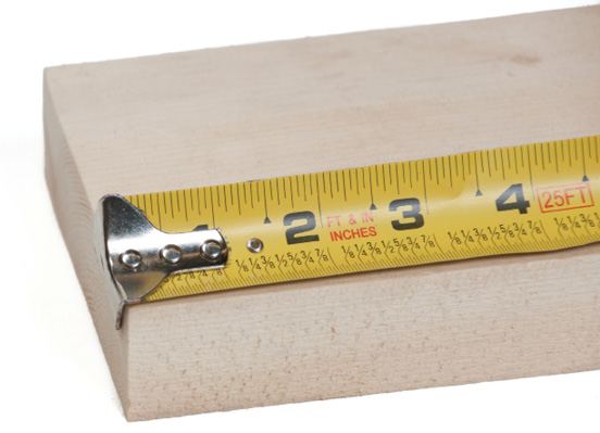
Figure 9 – Tape measure with movable hook
To avoid any error and in order to place the tape flat on the drawing, use a convenient unit mark, such as 100 mm, as the starting point for measuring, as in Figure 10.
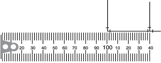
Figure 10 – Measuring metric drawings
The distance between the dimension lines is 40 mm. Since the scale is 1:50, the centre-to-centre length is:
40 mm × 50 = 2000 mm
If the scale had been 1:100, the length would be 40 mm × 100 = 4000 mm.
Follow the same procedure to determine approximate lengths from imperial scale drawings. An imperial tape measure is used in the same way to find a length on the drawing in inches. As an example, suppose the length is 7½”. To find the length represented, use the scale of the drawing.
In every case, if you divide the length on the drawing by the scale fraction or number, you will be calculating the length in feet. Since dividing by a fraction is the same as multiplying by its reciprocal, you multiply the drawn length in inches by:
4 when the scale is ¼” = 1′-0″
8 when the scale is 1/8” = 1′-0″
2 when the scale is ½” = 1′-0″
The reciprocals of all standard scales used by architects are shown in Figure 11.
|
Scale |
3/32 |
1/8 |
3/16 |
1/4 |
3/8 |
1/2 |
3/4 |
1 |
1 1/2 (3/2) |
3 |
|
Reciprocal |
32/3 |
8 |
16/3 |
4 |
8/3 |
2 |
4/3 |
1 |
2/3 |
1/3 |
Figure 11 – Reciprocals of standard scales
The 7½“ length on a drawing scaled ¼“ = 1′-0“ would represent 7 ½” × 4 = 30′.
On a scale of 3/8“ = 1‘-0“, the same 7 ½“ drawing length would represent 7½” × 8/3 = 20′.
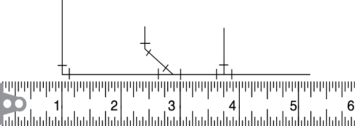
Figure 12 – Reading lengths of piping runs
Figure 12 is part of a piping run drawn to the scale of 1/8“= 1′ -0″. The total length of the run is 4¼” × w8 = 34″.
Self Test
![]() Now complete the Learning Task Self-Test.
Now complete the Learning Task Self-Test.
![]() Key Takeaways
Key Takeaways
- There is a precise relationship between the size of the drawing elements and the actual object portrayed in the drawing.
- An Architect’s scale is used for imperial measurements and allows easy reading of feet and inches. A Metric scale is used for metric measurements and allows for the reading of decimal points.
- The actual dimension can be determined from a scale drawing using the appropriate scale on a scale ruler.
